I spent some time making the rounds on social media and saw a lot of confusion over what is ATX 3.0, what is PCIe 5.0 and what is a 12VHPWR connector and how they work. There's also a bit of my own opinion about the connectors in this piece as well. So don't take this as a "review of the 12VHPWR connector" but rather an "opinion piece".
First off, PCIe 5.0 and the 12VHPWR connector are not Intel spec. It was developed by the PCI-SIG for a spec sponsored by Nvidia and Dell. It appears in the Intel spec after the fact because Intel had to make it part of the spec since the PCI-SIG were requiring consumer to use the connector for powering graphics cards.
Here's a screenshot of the title page of the 12VPWHR specification document:
WHAT IS ATX 3.0
- ATX 3.0 was was released in February 2022. It is an accumulation of new specs from draft ATX12V specifications dating back to 2020 as well as the 12VHPWR connector that PCI-SIG had introduced in November 2021.
- Reflects power excursions into section 3.1 of Chapter 3 as defined in the PCIe 5.0 add-in card spec of November 2021.
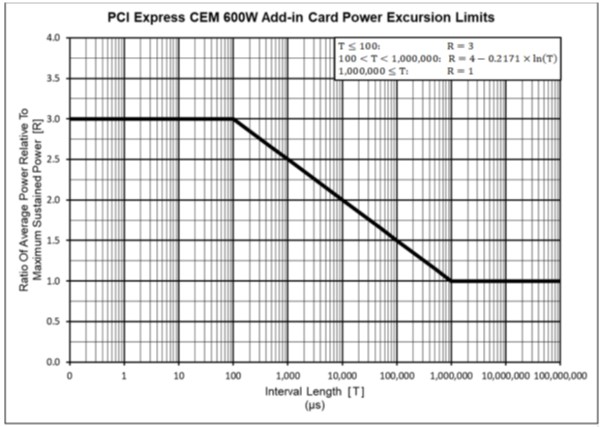
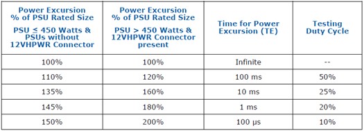
- ATX 3.0 adds a PSU “Power Budget” (table 3-3) that shows a PSU equipped with a 12VHPWR connector should support 200% of it’s continuous output capability for 100μs, 180% of it’s continuous output capability for 1ms, etc.
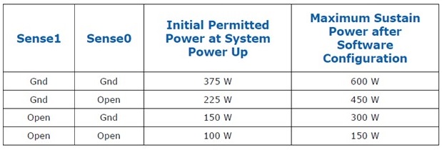
- ATX 3.0 adds the 12VHPWR connector’s sense pin configuration in section 3.3 of Chapter 3 as defined in the PCIe 5.0 add-in card spec of November 2021.
- Sense1 and/or Sense0 are required (3.3.1) for 300W, 450W and 600W GPUs. Note that the table says "Gnd". That's short for GROUND. You GROUND these pins in the circuit. There is no intelligence here.
- CARD_PWR_STABLE and CARD_CBL_PRES# are optional (3.3.2 and 3.3.3)
- CARD_PWR_STABLE is like the PWR_OK on your 24-pin. This allows the GPU to inform the PSU that everything is ok with the power delivery.
- CARD_CBL_PRES# actually “reports” to the PSU that a card, or cards are present, and that the PSU should budget power accordingly; assuming the PSU has the ability to support this.
- Section 4.2.1 of Chapter 4 states that nominal voltage can be increased from 12V to 12.1 or 12.2V to better handle power excursions. Furthermore, that +12V rail can now drop as much as -7% (11.2V), as opposed to previous -5% (11.4V) to allow lower output voltage during power excursions.
- An ATX 3.0 PSU is required for a PCIe 5.0 graphics card
- The PCI-SIG specification for PCIe 5.0 and use of the 12VHPWR connector does not tie itself to any Intel ATX standard. In fact, it pre-dates the ATX 3.0 specification by three months.
- Four sense wires on the PSU side are required for proper 12VHPWR functionality.
- Only two wires are required for definition of 300W, 450W and 600W cards. Depending on what sense pins are grounded, the GPU shall not use more power than is designated by the PSU. The result of a “lower power” cable paired with a “higher power” card can result in the card either not posting, or the card operating at a speed that is not representative of its fully potential.
- Wanting to avoid a < 30mm bend radius is a real thing. But it’s not 30mm up or down (North or South) that is a problem. Which is good news for the GPU side of the cable since that’s how most people route their GPU cables.
But on the PSU side, left or right (West or East) routing is more common because the PSU is under a shroud, with the connectors facing front. The cable has to make an egress towards the back of the chassis (typically, though some chassis you can go straight up the front) and along the back of the motherboard tray to eventually find its way to the GPU.
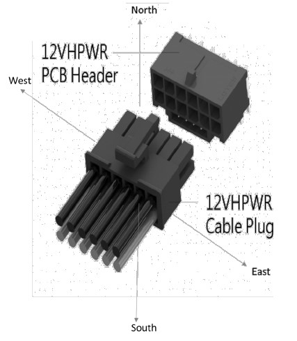
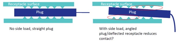
When you bend left or right (West or East) across 10 terminal rows, you create slack at the inside of the bend and tautness on the outside of the bend. That tautness can cause the terminals to tilt at an angle increasing the resistance at that terminal.
And in some extreme cases, you can actually have the terminal pop out completely when bending East or West.
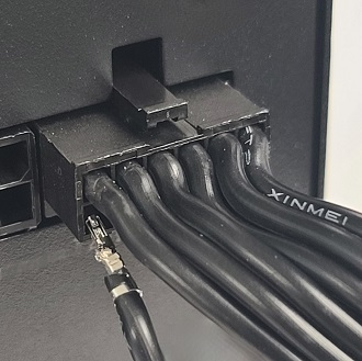
For the record: The connector on the left was "repaired" by pulling out the terminal completely and fixing the barbs. The one on the right would not push back in. After pulling it out to look for damaged barbs, we found the terminal in good shape. Despite this, it would not lock back into place. So we have to assume the connector is damaged on the inside.
- Remember what I was saying about the PCB layers and copper density being part of the solution? Well, when I was in Taiwan recently, I had the opportunity to ask a few of the OEMs what they were using for the modular PCB that was currently sporting the 12VHPWR connector on them. The typical answer was 4 layers with 2oz copper. That’s actually quite normal for a PSU PCB. Normally you have multiple connectors spread across a larger area. But now we’re expected to move twice as much power in the same amount of space as a single 8-pin connector. Umm… no thanks.
- As with the connector on the GPU side, the same is true with the connector on the PSU side. If the connector is not installed where it is completely flush and the latch securely locked in place, the connector could potentially "wiggle out", causing high resistence and result in burning.
MYTHS:
IF ONLY TWO SENSE WIRES ARE USED ON THE GPU SIDE, WHY DOES THE NVIDIA ADAPTER HAVE FOUR ON THE PSU SIDE?
Each 8-pin PCIe connection has a sense wire. The GPU side has two. There is an IC that “detects” how many 8-pins are plugged in and in-turn, terminates one or two of the sense wires on the GPU side to ground to “tell’ the GPU that it can handle either 450W or 600W.
WHY DOES NVIDIA USE FOUR 8-PIN CONNECTORS, WHILE OTHERS, LIKE CORSAIR’S AND SEASONIC’S, ONLY USE TWO?
The 12VHPWR connector supports 16g wire. But not every PSU maker uses 16g wire for their PCIe cables. Furthermore, there are many different specs for the materials for the terminal and connector. So Nvidia is doing a “CYA”, taking into consideration that you might be using some cheaper PSU with sub-standard cables and wants to make sure the problem is not on their end.
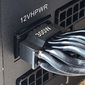
As for “native” cables that use two 8-pins on the PSU side: What we’re seeing here is simply a one-to-one connection between the PSU and the 12VHPWR connector. Six 12V to six 12V. Six grounds to six grounds. Two sense wires to two grounds. No CARD_PWR_STABLE and CARD_CBL_PRES# because they are not used.
BUT AREN’T 8-PIN PCIe CONNECTORS LIMITED TO 150W?
Not really. This was, like the current 8-pin adapter, a “catch all” spec that the PCI-SIG put into play back in January 2007 that took into consideration the many variables in the implementation of the PCIe cable, connector and terminals used. That could include various terminal material, various connector material, various gauge of wire used, etc. As well as the implementation of different PCBs, the number of PCB layers and the weight of the copper. Keep in mind that back in 2008 when the GeForce GTX 280 appeared with an 8-pin power connector, PSUs were a lot less robust. You could essentially make an 8-pin PCIe connector that can only support 4A per terminal using 20g wire with phosphor bronze terminals if you really wanted to.
A quality PSU like a Corsair, Seasonic, beQuiet, etc. will tend to use what is called Mini-Fit HCS (stands for “High Current System”). These terminals are specified to support 8.5 to 10A of current each (see dual row with 16 AWG and 18 AWG wire in the Molex Mini-Fit PLUS HCS spec). This makes the connectors actually more capable than the 12VHPWR connector. Even if Mini-Fit Jr. is used instead of HCS, the rating is A LOT higher than 150W per connector.
THEN WHY DO SOME COMPANIES THAT USE QUALITY COMPONENTS STILL USE MULTIPLE 8-PIN CONNECTORS?
Heat dissipation is the primary reason. Not only does your power cable move power, which creates resistance, which creates heat (by the way… fun book: https://www.amazon.com/There-Are-Electrons-Electronics-Earthlings/dp/0962781592 No, it’s no an affiliate link) but power has to move across the PCB. If your PSU’s modular board is 8-layer using 4oz copper, then you’re probably never going to have any measurable resistance. 6-layer 3oz is even fine. But while multiple PCB layers and higher copper density works better, it costs money. You can remedy this by just using fewer layers and less dense copper over a larger surface area. Take a PowerColor Red Devil 6900 XT just as an example. The card needs upwards of 360W but has three 8-pin power connectors. The card doesn’t need anywhere near that many connectors, but by using that many, they are spreading the power, and therefore heat, across a larger surface area. This is an example of the PCB acting like a heatsink. The more surface area, the better.
WAIT…. SO, ISN’T THIS A PROBLEM WITH THE NEW 12VHPWR CONNECTOR?
Well… yes and no. The specification for the connector and its terminals to support 450 to 600W is very precise. You are only within spec if you use glass fiber filled thermoplastic rated for 70°C temperatures and meets UL94V-0 flammability requirements. The terminals used can only be brass, never phosphor bronze, and the wire gauge must be 16g (except for the side band wires, of course). Unlike previous connectors on the market, there is no “pass” allowed to make cheaper connectors. If you make your cable any other way, you are not "within spec".
But there is an issue with the size of the terminals and their density. You are pulling more power through a smaller area, and this is going to generate more heat. But again, the connector is rated at 70°C based on the materials used. Even the best Mini-Fit Jr. connector directly from Molex is only good for 65°C.
So that brings us to the construction of the GPU. Historically, 12 to 14-layer PCBs are used with higher end graphics cards. Hopefully in time someone with the actual specifications for a 4090 PCB can reach out to me and I can update this article (confirmed that it's 14-layer, but copper density unknown). But I'm 99.9% positive that the graphics card's PCB is more than adequate for the card's power requirements with "normal" heat dissipation expectations. The reason why I'm even bringing this up witll come later....
SO, YOU’RE GOOD WITH THE 12VHPWR CONNECTOR?
Yes and no. I’m good with the connector on the GPU side as long as “rules” are followed. Proper material. Proper crimp. Proper wires. And I’m sure most GPUs out there have proper PCB layers, copper weight, etc.
Unfortunrely, a number of connector failures have cropped up since the launch of the 4090.
(BTW: This was me being quoted by PC Mag):
The connector itself is potentially good. I say "potentially" because it is very difficult to install. If the connector is not installed where it is completely flush and the latch securely locked in place, the connector could potentially "wiggle out", causing high resistence and result in burning. There are very few examples of this compared to the number of graphics cards in the field, but it goes without saying that when you spend $1500 on a graphics card and the power connector melts, it can be pretty upsetting. Telling people that "user error" is the reason for failure is a good way to piss people off. A connector like this should be more "idiot proof". Therefore, we can still fall back to this being a "design issue".
For now, let’s assume everything is good on the GPU side and you have an actual "native cable" (a cable that has 12VHPWR on both sides) going directly from the PSU to the GPU. Good, right?
WELL…… NOT QUITE.
There are still two things that bother me about putting the 12VHPWR on the PSU side…
In conclusion, 12VHPWR is fine.. like I said months ago. But for now I will stick with only using them on the GPU side. And I make sure the connector is fully installed and latched by installing the cable to the graphics card BEFORE installing it in the PC.
Of course, if the time comes where the CARD_PWR_STABLE and CARD_CBL_PRES# are actually used and we have to use all four wires of the sideband connector, we'll have to be forced to use the 12VHPWR connector on the PSU side. Let's hope that never actually happens.