Introduction
I became head of the tech support department of an online retailer in Tampa, FL. My role involved assisting customers in assembling their own mix-and-match PCs that would run faster and cost less than those sold at department stores. It was 1999, and AMD reigned with their K6 and Athlon processors. Motherboards from brands like Abit, MSI, and Asus were selling rapidly. However, power supplies weren’t as popular with our customers. Some would say they were “too expensive”.
Our company offered technical support via phone, email, or online chat, along with a one-year warranty. We also built PCs that we offered two year warranties on. This level of service meant we had to make sure we had a lot of trust in the products we were selling. Very early on we would find that the component we saw fail most often was the cheap power supply typically found pre-installed in most cases. Thus, we chose to stock only high-quality power supplies from brands like Antec, Enermax, and Super Flower. While most of our sales happened online and were shipped worldwide, we had a bustling will-call counter for local pickups. Just down the street was a smaller rival focusing on low-cost PC builds. The most popular setup was Cyrix CPUs on ECS motherboards. They offered Powmax and Raidmax power supplies, with Diablotek and Aspire (now Apevia) reserved as their "high-end" options—though these 'high-end' units were still inferior by build quality and performance by most standards.
In the past, much like today, power supplies were often seen as mysterious "magic boxes filled with capacitors" that couldn't be easily evaluated. If the label claimed "550W," then it was assumed the PSU (short for "power supply unit") delivered 550W. As long as it provided DC power after being plugged in and switched on, any concerns about its performance and durability seemed irrelevant. Or were they?
A few years down the line, we noticed more and more motherboards coming back within a year with swollen capacitors. This struck me as strange since none of the PCs we built had this problem. The common factor in these cases was the use of cheap power supplies, typically the ones bought from our friends down the street. I know some of you might mention the capacitor plague happening during this time frame. I'm not denying its existence; it was real. I was aware then, as I am now, of the susceptibility of Abit motherboard capacitors failing and the failures that occurred with certain Antec power supply models. This is something I'll discuss later in this article.
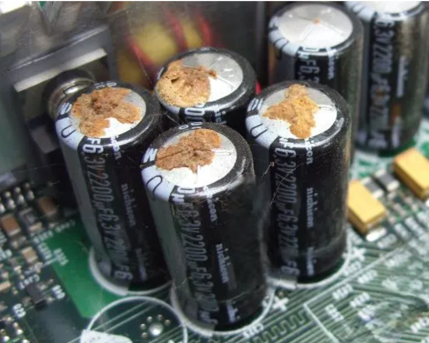
Even Nichicon capacitors are not prone to bad power.
The particular failures we were seeing with our motherboards were due to something more insidious: AC ripple current and the power supply's failure to adequately filter it out.
What is ripple, why is it bad… and how did it change my career path
Within my circle, "box of caps" is an inside joke used when we see laymen troubleshooting potential power supply issues with their PCs. Whenever a power supply fails, the common assumption on social media is that "a capacitor must have popped." If there's smoke, it's assumed to be magic smoke from a capacitor. A spark? A capacitor exploded. When RTV is spotted on the PCB, people think it's not RTV but electrolytic fluid leaking from a capacitor. For many, the workings of a power supply remain a mystery. Adding to this is the constant warning that opening a PSU could lead to electrocution, maintaining the enigmatic nature of power supplies for most consumers.
A power supply isn't merely a collection of capacitors. And while opening a power supply isn't likely to be fatal, caution is necessary, especially with the large capacitors on the primary side of the PSU. They can indeed be dangerous, though such incidents are rare. But it's wise to avoid rare, potentially deadly situations, much like not dozing off on train tracks—it's just not smart.
XKCD comic strip from https://xkcd.com/3106/
Thankfully, capacitors can be discharged easily. Many power supplies come with bleed resistors to safely discharge stored energy over time, reducing shock risk. And in 2020, the IEC mandated the inclusion of bleeder circuits in power supply designs.
I chose to write this article with a focus on capacitors, as they seem to be the most widely understood component; and because it’s the reason I moved into reviewing power supplies, and then later marketing and eventually designing them.
As I stated earlier, my journey in the power supply industry began with motherboards with swollen caps that didn’t happen to be victims of the capacitor plague. It wasn't until a couple of friends from Antec explained the situation that I made the connection. But before I move to how that all transpired, allow me to explain AC ripple current (or just “ripple” for short) and why it’s important to keep it in check.
When converting AC to DC, AC becomes a part of the DC output. In a switch-mode power supply, not only do we receive AC from the wall, but during the process of converting AC to DC, back to AC, and then finally back to DC again, generates high-frequency noise and harmonics.
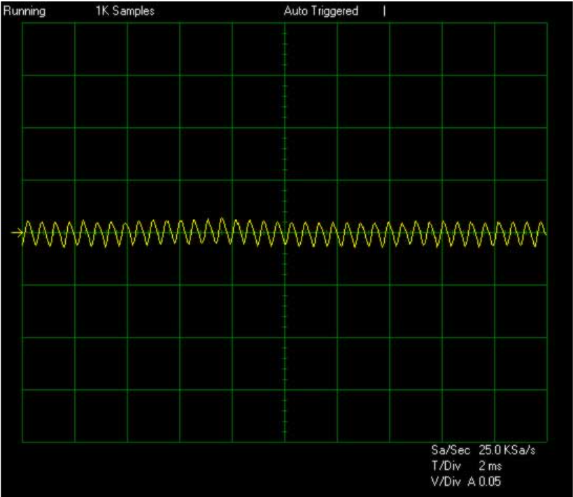
This is a screenshot from an oscilloscope of AC ripple on a DC output.
High ripple can cause the capacitors in your devices to overheat, leading to the evaporation of the electrolyte and potential catastrophic failure. Capacitors rated at 105°C can handle AC ripple longer than the standard 85°C ones, so high-quality motherboards use them to reduce the risk of failure. Polymer aluminum capacitors, also known as “solid caps,” are a reliable choice due to their high ripple current rating (often noted as "Ripple Current @ High Frequency") and are typically rated at 105°C or higher.
The smaller capacitors on the output side of a power supply help filter out as much ripple as possible. However, increasing their capacitance in an attempt to filter out more ripple also raises the in-rush current because all of these capacitors need to be fully charged to reach the desired output voltage. Output voltage regulation can be affected when power excursions, or "transients", as some people call them, partially drain the capacitors, requiring them to recharge to maintain proper output voltage. This also stresses the switching components. So it’s best to find the right balance of capacitance and acceptable filtering.
When we experienced motherboard failures due to the use of cheap power supplies, a couple of guys from Antec demonstrated to me how to use a load tester to apply a simulated load on the PSU, along with an oscilloscope to measure the ripple. They began by showing me an Antec PSU, which had a ripple of only about 50mV at full load. We then replaced it with one of the inexpensive PSUs from the computer store down the road. Not only was it unable to handle a full load, but even at half the load stated on the label, the ripple soared to around 250mV. Far above safe thresholds for most consumer electronics.
It was then that I decided to invest in a SunMoon SM-268 and an analog Tektronix oscilloscope. For AC input, I used a large variac that was half a meter tall and an IDRC power meter. This marked the beginning of my journey in reviewing PSUs and challenging the "box of capacitors" concept.
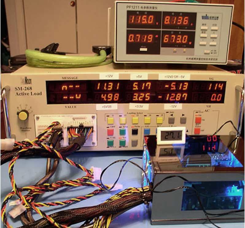
My old SM-268 setup from around 2005.
What is a capacitor?
An electrolytic capacitor utilizes an aluminum foil (although smaller, more expensive caps use tantalum) as its anode, which is often referred to as a "plate." This “plate” is typically between 20 and 100μm thick and should be at least 99.99% pure. This aluminum foil undergoes etching and is coated with aluminum oxide, which serves as the insulating dielectric material. The etching process increases the surface area of the foil compared to a smooth piece, thereby enhancing the capacitance value.
A second piece of aluminum foil acts as the negative electrical plate of the capacitor. Between this foil and the dielectric oxide layer is a paper material soaked in liquid electrolyte which functions as the physical cathode for the capacitor. These two metal plates, the anode foil and cathode foil, along with the electrolyte-soaked paper, are wound together inside an aluminum can, which is then covered with an insulating sleeve.
To form the initial dielectric oxide layer, a positive voltage is applied to the etched anode foil in an electrolytic bath. This process creates a dielectric oxide layer on the anode foil, with its thickness corresponding to the applied voltage.
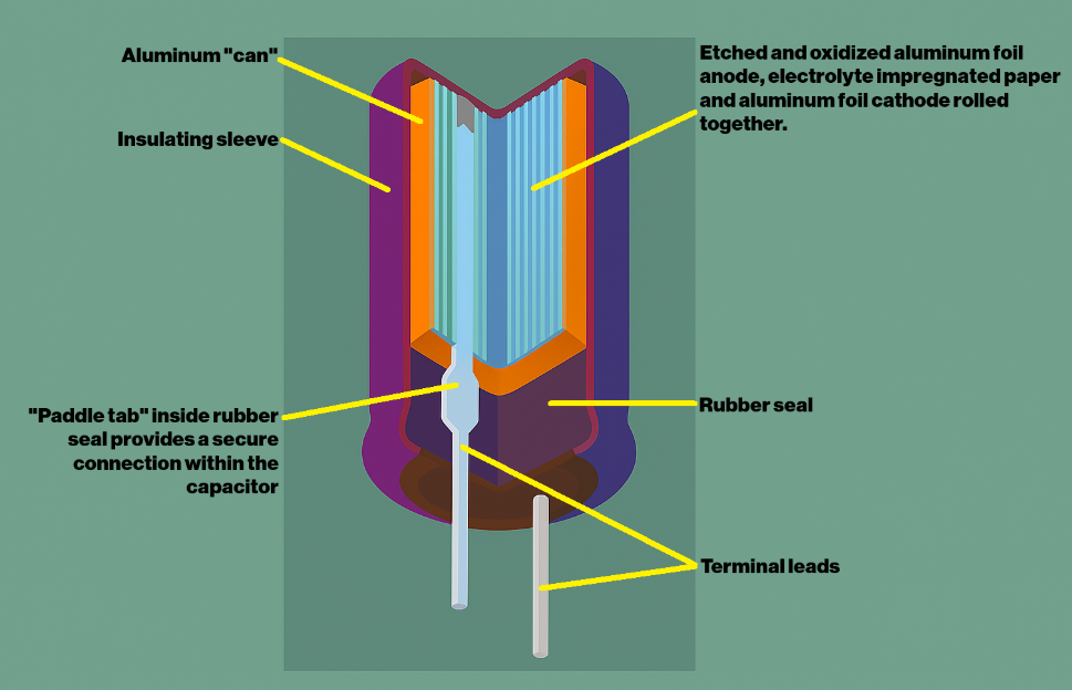
Diagram showing the inside of an aluminum electrolytic capacitor.
When DC voltage is applied to the capacitor, the dielectric generates a magnetic field that produces a polarized charge between the two electrodes. However, the dielectric oxide layer can have imperfections, allowing the possibility of current leakage, known as leakage current, after applying the correct polarity DC voltage. Because the oxide layer is formed by applying voltage to the anode, if capacitors remain unused for extended periods without voltage, the dielectric oxide layer can degrade. The acidic electrolyte reacts with the oxide layer, breaking it down. As this deterioration progresses, leakage current increases when the rated voltage is applied. Excessive leakage current through the capacitor with a degraded dielectric can ultimately lead to capacitor failure.
I’ve seen some people refer to the bulk capacitor in a PSU as a “super capacitor.” This is a misunderstanding. The bulk capacitor is not a super capacitor; it is simply a large aluminum electrolytic capacitor designed for high-voltage filtering. While these bulk capacitors are physically large and have relatively high capacitance compared to other components in the circuit, they are fundamentally different from super capacitors in both construction and application.
Super capacitors use electrodes with extremely high surface area (often made of activated carbon) and are separated by an electrolyte-soaked separator without a true dielectric layer.
Super capacitors aren’t used in SMPSs for a number of reasons. First, the capacitance tends to be in the milliFarads and Farads as opposed to microFarads. Also, the voltage ratings tend to be quite low; like in the neighborhood of 3 to 11V. In contrast, aluminum electrolytic capacitors used in PSUs typically offer capacitance values in the hundreds to thousands of microfarads, but are rated for much higher voltages.
Another issue is that super capacitors generally have lower temperature ratings—typically around 60°C to 70°C, with some industrial versions rated up to 85°C. This is often insufficient for the high thermal stress environments of switch-mode power supplies, especially in PCs, where 85°C to 105°C rated capacitors are already considered the minimum acceptable for long-term reliability.
The “Capacitor Plague”
In the early 2000s, PC builders and repair technicians began noticing an unusually high incidence of motherboards whose electrolytic capacitors were bulging, leaking, or even bursting—a phenomenon soon dubbed the “capacitor plague.”
According to industry rumora, a team of researchers formerly employed by Japan’s Rubycon Corporation defected to Taiwan’s Luminous Town Electronics (LTEC). There, they reverse-engineered Rubycon’s P-50 water-based electrolyte and used it successfully in their own aluminum electrolytic caps.
As a footnote: LTEC was purchased by Kamei Electric and rolled into their portfolio with Teapo and Jamicon.
Shortly thereafter, some of those LTEC scientists left, carrying an incomplete version of the P-50 formula. They sold it—either directly to other Taiwanese capacitor makers or to an electrolyte supplier who in turn resold it. Because key additives known as “depolarizers” were missing, the compromised electrolytic mix generated hydrogen gas inside the caps until they ruptured. In addition, the formula’s elevated pH corroded the aluminum plates, degrading the capacitor’s ability to hold charge.
The tainted electrolyte was found in capacitors from numerous brands, including: Jun Fu, Choyo, Chhsi, G-Luxon, Evercon, Sacon, Lelon, Licon, Tayeh, CapXon, Jackcon, JPCON, and Rulycon (not to be confused with the legitimate Rubycon).
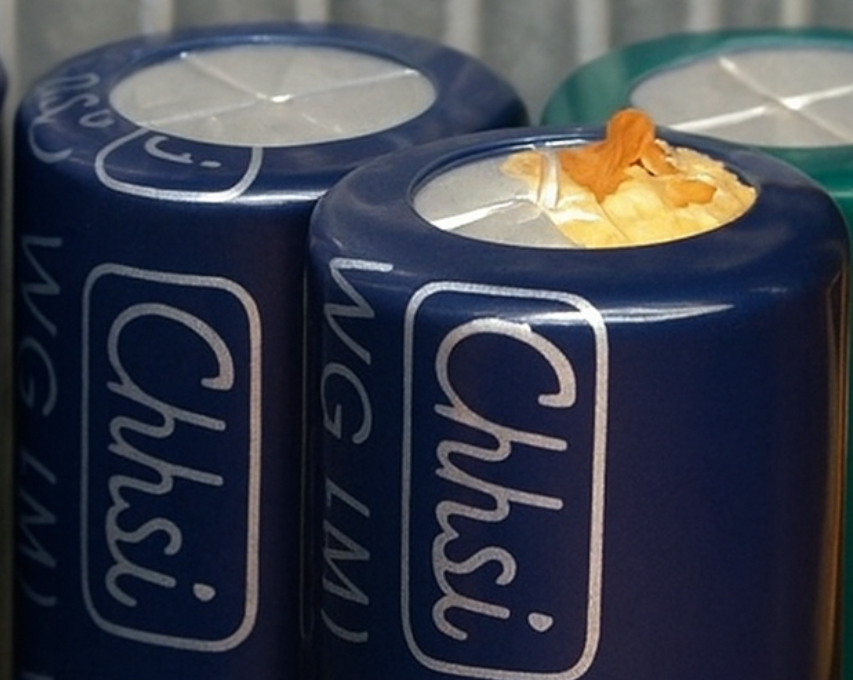
A venting Chhsi brand capacitor. These were known to have the “stolen electrolyte formula” which caused premature failures.
IBM was the first major PC maker to acknowledge using these capacitors, though it downplayed the issue by reporting only about a 1 percent failure rate. Soon afterward, in 2005, motherboard manufacturer Abit admitted to using capacitors with the incomplete electrolytic formula and announced it would switch exclusively to Japanese capacitors. Unfortunately for Abit, this “admission of guilt” prompted a class-action lawsuit alleging deceptive practices.
One of the more notorious cases of failed capacitors involved Antec’s power supplies outfitted with Fuhjyyu capacitors. At the time, experts insisted those caps hadn’t used the stolen P-50 formula and attributed failures instead to inadequate airflow or suboptimal circuit designs that demanded different capacitance values. Based on my own experience, that explanation makes sense. I’ve even seen brand-new, unopened PSUs develop leaky caps simply from sitting in a hot, humid warehouse—proof that even top-quality electrolytics can degrade over time under harsh storage conditions. And, of course, we must not forget that a power supply actually has quite a few miles on it before it even leaves the factory. Every power supply gets full testing on test equipment, hi-pot testing, and burn-in in high temperature cabinets delivering a 75% load to the PSU over the course of 4 to 8 hours. This alone could potentially cause capacitor failure if there is a problem with the power supply’s design.
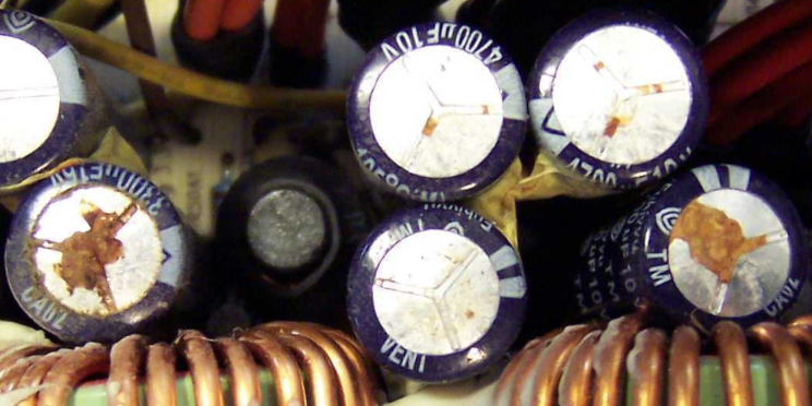
A number of leaking Fuhjyyu capacitors inside an Antec True Power power supply.
I’ve encountered design-related capacitor failures myself. Over a decade ago, a project I worked on specified a SamXon bulk capacitor. A flaw in the power factor correction inductor caused it to saturate, and the resulting stress made the bulk cap fail. End users, many of whom view a PSU as nothing more than “a box of capacitors,” immediately blamed the capacitor plague—despite the fact that SamXon was never implicated in any electrolyte scandal and that the incident of the failed bulk caps happened a decade after the capacitor plague occurred.
Today, the original capacitor plague is firmly in the past, but its shadow lingers. Mention CapXon, G-Luxon, or Lelon, and many people still recoil, convinced they’re dealing with “bad caps” destined to fail because of a flawed electrolyte recipe.
What’s the deal with Japanese Capacitors?
I’m hoping you said that in Jerry Seinfeld's voice.
As previously mentioned, following the capacitor plague, some vendors pledged to use only Japanese brand capacitors to assure customers they wouldn't face issues due to faulty electrolyte formulas.
However, much has changed since those days. Electrolyte formulas have largely stabilized and improved over time, and both materials and quality control have seen significant advancements. That doesn't mean there aren't still some cheap imitation capacitors or small factories producing subpar products, but these are becoming increasingly rare.
One thing a lot of people don’t seem to understand is that most capacitors used in products made in China today actually use Chinese made capacitors; even if they have Japanese branding on them.
Many people don't realize that most capacitors in products made in China today are actually Chinese-made, even if they carry Japanese branding. China imposes a Value Added Tax (VAT) of around 13% on most goods shipped into the country, along with a 13% tariff. Considering these costs, along with the logistics of shipping, it makes sense to either partner with the Chinese government to establish a factory in China or collaborate with an existing Chinese manufacturer to produce capacitors.
This isn't to say that every reputable Chinese capacitor factory can produce capacitors on par with those from a Japanese factory. However, every capacitor brand offers a wide range of products, and it's the engineer's responsibility to ensure the capacitor they select is suitable for its application.
Over the past ten years and more, I've grown increasingly at ease with the use of capacitors from non-Japanese brands. Apparently, I'm not the only one. Hitachi relocated its electrolytic capacitor production to China in 1999, partnering with the Nantong Jianghai Capacitor company. By 2020, Hitachi exited the industry entirely by selling all its interests in the development of aluminum electrolytic capacitors to Nantong Jianghai. Many engineers who previously relied on Hitachi capacitors now use Jianghai capacitors without any reservations.
As for me, I personally prefer the Teapo TB series and Elite PF series capacitors, both Taiwanese brands typically manufactured in China, for the secondary side of a PSU. But because of the "long memory of the Internet," marketing departments still insist on using Japanese brand capacitors in most projects so they can highlight "Japanese capacitors" as a selling point on packaging and promotional materials.
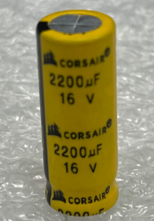
A CORSAIR branded Elite capacitor. These are currently in production, but not in the “CORSAIR yellow” color.
Capacitor shelf life
Since we’ve been talking about capacitors for the bulk of the beginning of this article, we might as well discuss capacitor life and the impact a stored capacitor, or power supply, has. The effects of storing discharged capacitors are often overlooked. This doesn't just apply to a collection of new capacitors on a shelf but also to those already installed within a power supply.
Even under ideal storage conditions — temperatures between 5° and 35°C and relative humidity below 75% — a PSU might only be fine for up to three years. However, if it has been kept in a place like an attic or garage during summer, the situation might be completely different.
So what happens as capacitors age? High humidity can lead to corrosion. And at elevated temperatures, the leakage current and equivalent series resistance (ESR) increase, while the capacitance and rated voltage decrease. These changes occur due to a chemical reaction between the oxide layer and the electrolyte. Applying the rated voltage to a long-stored capacitor could result in the dielectric breaking down and the relief vent eventually popping open.
For those technically inclined to do so, a capacitor can be “reformed”. This process is done with the capacitor removed from the circuit. I’d also like to add that this process should only be attempted by experienced individuals with proper safety precautions.
Reforming involves gradually applying power to the aged capacitor. You connect the capacitor to a resistor placed between its negative leg and the negative terminal of a bench power supply. Start with a voltage lower than the capacitor's rating. Depending on the rated voltage of the cap, I would suggest 1/3rd to 1/5th the rated voltage. Let it sit for an hour at this lower voltage, then increase the voltage and let it sit for another hour. Repeat this process until the capacitor reaches its rated voltage. Leave it overnight at this level. The next morning, check the capacitor with an ESR/LSR (Equivalent Series Resistance / Leakage Series Resistance) meter to ensure the equivalent series resistance and leakage current meet specifications. If everything is in order, discharge the capacitor and reinstall it into the circuit.
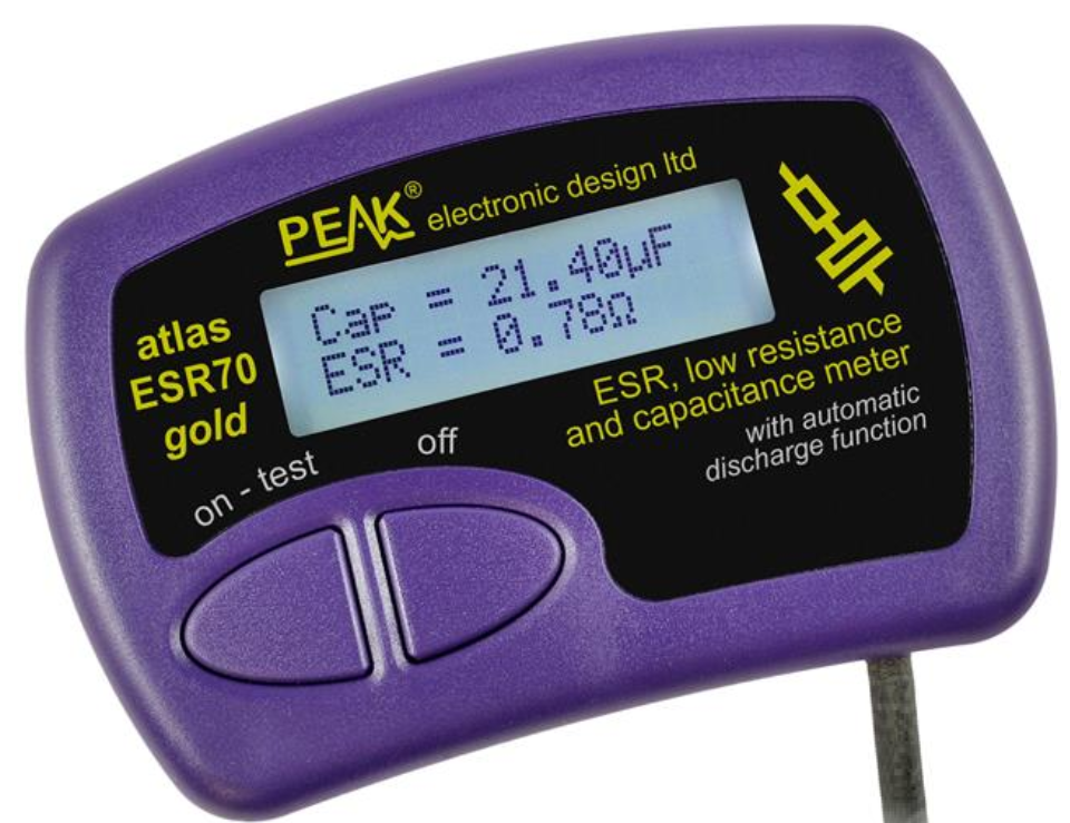
PEAK makes an affordable ESR/LSR meter. Even if you don’t plan to reform, it’s a good tool to have around to at least check the condition of old capacitors.
Clearly, this process requires several tools. While many of my peers might have a bench power supply and a drawer full of random resistors, not everyone has an ESR/LSR meter handy. In my view, if you're going to the trouble of removing a capacitor from a circuit to reform it, you might as well replace the power supply with new capacitors.
In conclusion....
I'm about tapped out for tonight. I hope you found my article informative. I'll probably be back with some more PSU insights as time allows. In the meantime, thank you for making it this far in the article.