PSU Musings:
I've been in the PC PSU industry for over two decades, and I’m not exaggerating when I say I learn something new every week. In the process of creating new products, one uncovers a great deal about what should and shouldn't be done. However, cost and time constraints often limit what's realistically achievable. Sometimes, it takes a barrage of customer complaints to convince upper management to spend a little more to refine a product.
This article is a “wish list” of insights I’ve gained over the years—principles I’ve tried to apply whenever possible. Of course, when costs become a barrier, I can’t incorporate everything I'd like into a PSU design. Still, I hope others will find areas of potential improvement here, whether you're a fellow designer, a curious end user, or a reviewer assessing product quality. Ideally, this will help illuminate how one PSU can be better engineered than another, even if their specs seem comparable on paper.
Just a reminder, I write for fun, so this is as much for my amusement as it is for yours. That said, I do hope you find some valuable insights along the way. It never ceases to amaze me how something we take for granted as “of course this should be designed this way” can be an “aha moment” for others.
Only use toroid coil inductors. Never rod coil:
A toroid coil inductor consists of a ferromagnetic ring wound with copper wire. A rod coil inductor uses a cylindrical core wrapped along its length. The only real benefit of a rod core is lower material and labor cost.
Toroid cores, by contrast, generate less audible noise. The magnetic forces within do not cause bending in the core—only compression or tension—and their circular design offers better mechanical stability.
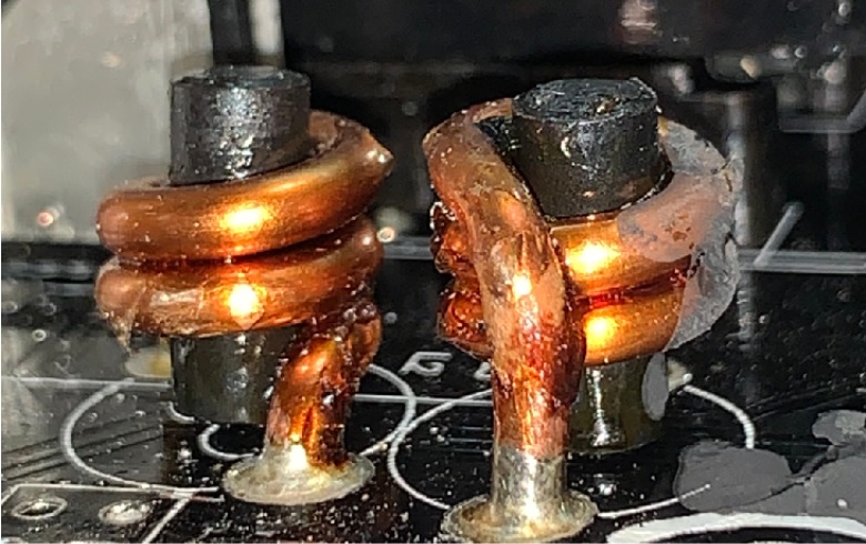
Pictured: A couple rod coils found inside a PSU.
The impacts of rod coils tend not to be evident in the lab. I once worked on a project that used rod coils on the output stage. Lab testing on our Chroma didn’t detect audible noise. But real-world usage told a different story: complaints came pouring in, and we quickly switched to toroids.
Using Sendust as a ferromagnetic material for your inductors:
Sendust is a magnetic alloy that was created as an alternative to iron powder and other magnetic core materials used in inductors and transformers. It is made up of 85% iron, 9% silicon, and 6% aluminum.
Sendust is highly regarded because it has lower eddy current losses and does not produce mechanical vibrations when exposed to magnetic fields. In our industry, the primary drawback is its cost. Additionally, since Sendust is a sintered compound, it tends to be more brittle than other materials. Consequently, Sendust inductors might need to be slightly larger to match the energy storage capacity of an iron core, so space limitations in smaller designs should be taken into account.
I’ve been using Sendust almost exclusively for about 10 years. I’ve found that the small investment made to improve audible noise is well worth it as customer complaints have been reduced significantly.
Using split-windings as opposed to single-windings:
Once again, we have an optimal solution that requires additional space. However, if space permits, I highly recommend using split-windings..
As the term suggests, a single-wound inductor consists of a single continuous copper wire coil wrapped around the core. A split-wound inductor, also called a bifilar-wound or common-mode choke, divides the copper wire into two separate windings around the core. This configuration effectively blocks common-mode noise, making it perfect for use as a PFC choke since it helps reduce EMI and RFI. Common-mode noise often arises from parasitic capacitances between the MOSFETs and ground.
Even though the split-wound inductor is larger, its cost should not significantly exceed that of a single-wound inductor, provided the manufacturing plant uses an automated process to produce them.
We started using the split-wound inductor for our PFC chokes when we started to see some high-frequency RFI results in some of our designs. Unfortunately, due to the slightly larger size, we can’t use them in smaller form factors like SFX.
Try not to use “Full Package” through hole (TO220FP) MOSFETs for PFC:
When working with smaller TO-220 MOSFETs, try to avoid using the "Full Package" for the primary side PFC switchers. The PFC MOSFETs tend to get much hotter than most other switchers in the power supply unit. Full package MOSFETs have relatively poor thermal conductivity because the plastic encapsulation inhibits direct thermal transfer from the die to the heatsink. This is similar to the difference between using a CPU with an integrated heat spreader (IHS) and one without or one that has been "delidded."
For a CPU without an IHS, effective heat transfer to the heatsink depends on a sufficient thermal solution. For this application, I suggest using a thermal pad that is very thin (less than 0.3mm) and has a thermal conductivity of 1.6W/m-K or higher.
Although the MOSFET itself shouldn't cost more, the assembly process is more complex, which will increase the overall cost of your build.
The only other option is to use the less common and more expensive TO-247, a larger package with more surface area for heat dissipation. Ultimately, the best solutions tend to be either larger, more costly, or both.
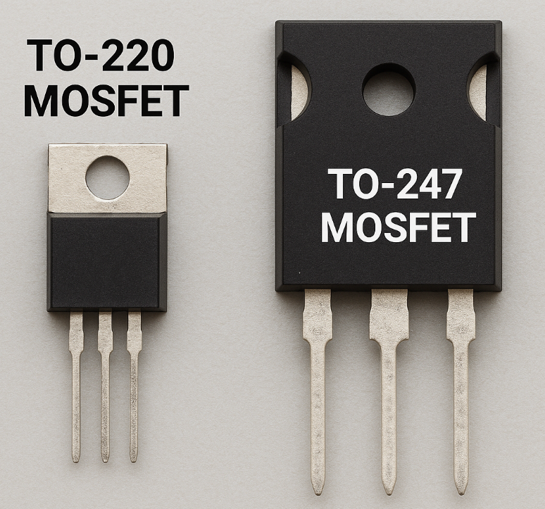
Size comparison of a typical TO-220 MOSFET and a TO-247.
Try to use MOSFETs for rectification instead of Schottky diodes (synchronous vs. passive rectification):
I'll be honest. I've often used Schottky diodes for 12VDC rectification in numerous projects with considerable success. They don't need any control circuitry and are fairly inexpensive. However, their efficiency is lower and they’re unsuitable for high wattage applications.
On the other hand, MOSFETs provide superior efficiency, better voltage regulation, and enhanced reliability compared to Schottky diodes in rectification circuits. Naturally, with these advantages, MOSFETs are pricier than diodes.
Utilize OTP on primary heatsink, as well as on the output rectification:
Typically there is only a temperature sensor on the rectification, which can typically run over 100°C at full load. But the primary side, particularly your bridge rectification, typically runs just as hot. Even hotter at lower mains voltage. While beefing up the bridge rectifier is one solution, it can be expensive. So it is a good idea to add an additional over temperature protection in the form of a thermal fuse as shown below:
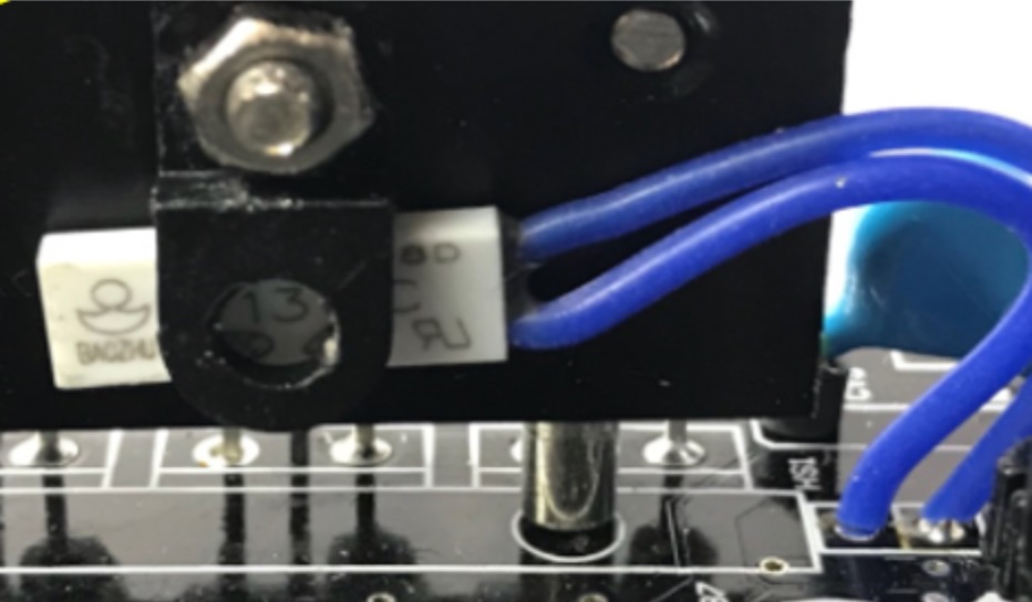
A thermal fuse mounted to the bridge rectifier's heatsink
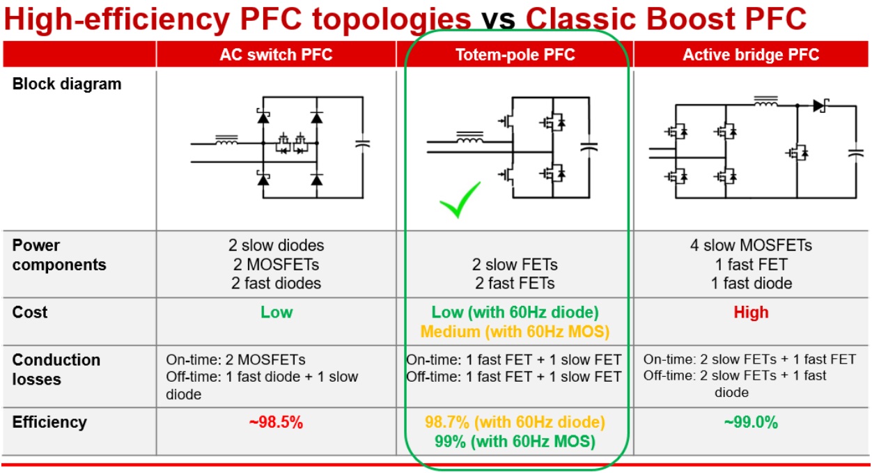
Use an active bridge or Totem-Pole instead of diode bridge…
The PFC circuit is where most of your losses occur. This is why you see totem-pole and active bridge used in more efficient power supply products. It just makes sense to move beyond 1990s-era designs and use a more modern, more efficient topology.
The below diagram from TI (taken from https://www.ti.com/video/5502515089001) shows the pros and cons of each:
Add thermistor or heatsinks to minor rails’ D2D for better fan control:
While the minor rails’ (+3.3V and +5V) D2D (DC to DC) in a PC SMPS does not typically get critically hot, they are often not equipped with heatsinks and can get somewhat warm when under load. Since they rarely hit temperatures that might lead to thermal runaway, it’s generally accepted to simply increase the fan speed based on the load on the rails rather than their actual temperature, as there is typically no thermistor on the D2D portion of the minor rails. By adding a temperature sensor to the D2D, you could achieve more precise fan control, provided a microcontroller unit (MCU) with an adequate number of input channels is used to adjust the fan speed.
Alternatively, or in addition, heatsinks could be attached to the D2D's MOSFETs. This is not commonly done since most D2D circuits are "drop-in" cards. Nonetheless, whether using aluminum heatsinks or attaching the MOSFETs to the PSU housing, both methods are possible.
However, there are drawbacks to these solutions. Heatsinks increase costs, and designing a PSU layout that allows the minor rails to dissipate heat to the housing would require a unique design that might need more space, as D2D boards are mounted perpendicular to the main PCB. The most effective way to heatsink the D2D without directly adding heatsinks to the MOSFETs or complicating the assembly would be to position the D2D on the underside of the main PCB, similar to how the +12V MOSFETs are often cooled, or place the D2D on the modular board.
ONLY use PWM fan controlled by an MCU and always use a better fan driver IC:
Using a PWM fan ensures the lowest possible RPM and more granular control, and therefore lowest noise possible.
However, reducing the duty cycle can introduce fan motor noise into the audible frequency range (below 20kHz). This typically happens when a driver IC.fails to generate a sufficiently smooth commutation waveform, which can introduce audible coil whine. Some better driver ICs can produce a quasi-sinusoidal output, and the closer this output is to a pure sine wave, the quieter the fan will be at lower RPMs.
Though it's common to use an MCU to control a PWM fan, these typically have a limited number of data input channels. If you follow my advice to use a thermistor on the bridge rectification and minor rail D2D, along with the +12V rectification, you'll need a more capable MCU. In most projects I've worked on, the fan speed increases not only with higher temperatures but also with higher loads. This requires channels to relay not only thermal information, but also the load information to the MCU so it can adjust the fan speed accordingly.
And, as with all my suggested improvements, PWM fans are more expensive, better driver ICs are pricier, and MCUs with additional channels cost more. Sorry. <(_ _)>
Utilize multiple supervisor ICs and/or MCU for multiple +12V OCP and allow the user to turn it on or off:
Nowadays, "multiple +12V rails" are essentially virtual, meaning there's only one physical +12V rail divided into multiple outputs, each with its own overcurrent protection. This setup effectively safeguards your PC in case of a short caused by wire damage or component burn-out. Without multiple OCP, if a short occurs on any device powered by the PSU, it can draw the entire rated current of the +12V rail until the PSU eventually shuts off, which can lead to significant damage before the OCP activates.
The challenge with implementing multiple +12V rails lies in the fact that the standard analog supervisor ICs used in most PSUs have a limited number of current monitoring pins to support multiple OCP. This constraint often forces PSU engineers to set the OCP trip points higher than ideal when incorporating multiple +12V rail OCP into the PSU.
By employing multiple ICs to increase the number of available OCP pins or by using a microcontroller with several input channels that can be dedicated to OCP, one can establish multiple "rails" with the same number of OCP points as there are modular connectors and set the OCP trip points at a reasonable level. Due to the sometimes deserved negative perceptions about multiple +12V rails because of poor PSU design, users might prefer to be able to switch between multiple and single +12V rail configurations. This is easily implemented.
Require soft termination MLCCs at particular “high risk” locations:
MLCC, which stands for Multilayer Ceramic Capacitor, is a widely used surface mount technology (SMT) capacitor found in electronic devices. These passive components store electrical energy and are mainly utilized for decoupling, filtering, bypassing, and timing tasks within circuits.
When an MLCC is positioned less than 2mm from the edge of a PCB or less than 3mm from a PCB screw hole, a soft termination MLCC must be employed. Failing to do so can result in these small components either breaking or detaching from the PCB, leading to intermittent connections.
For power supply units (PSUs) with modular PCBs that use MLCCs, it is recommended to exclusively use soft termination MLCCs. This precaution is necessary because the insertion and removal of modular cables can cause the PCB to flex, potentially damaging the MLCC or its connection to the board.
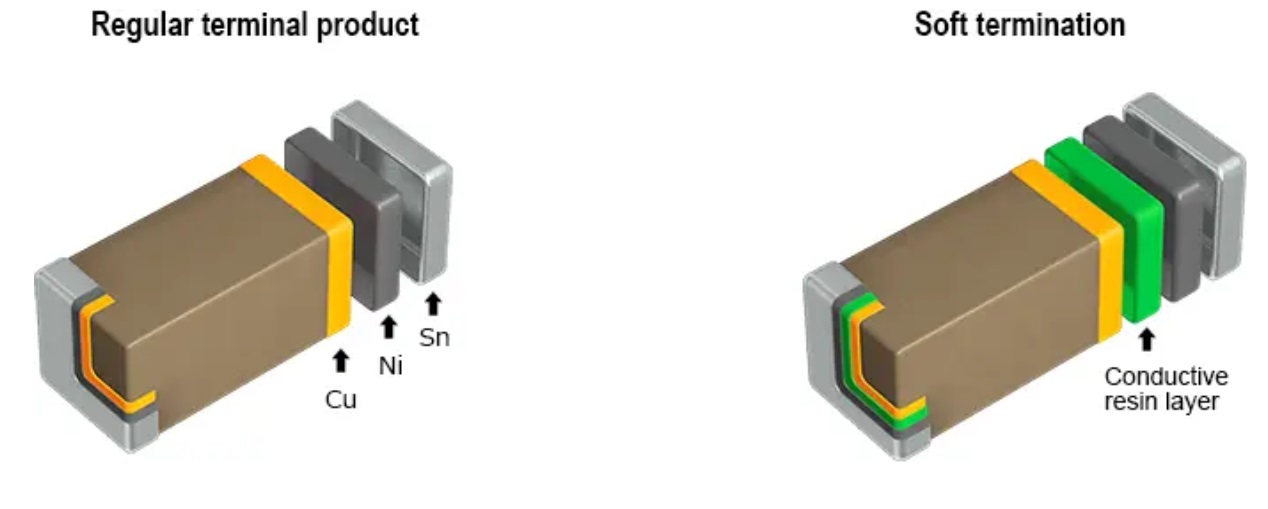
Comparison of a typical MLCC and one with soft termination
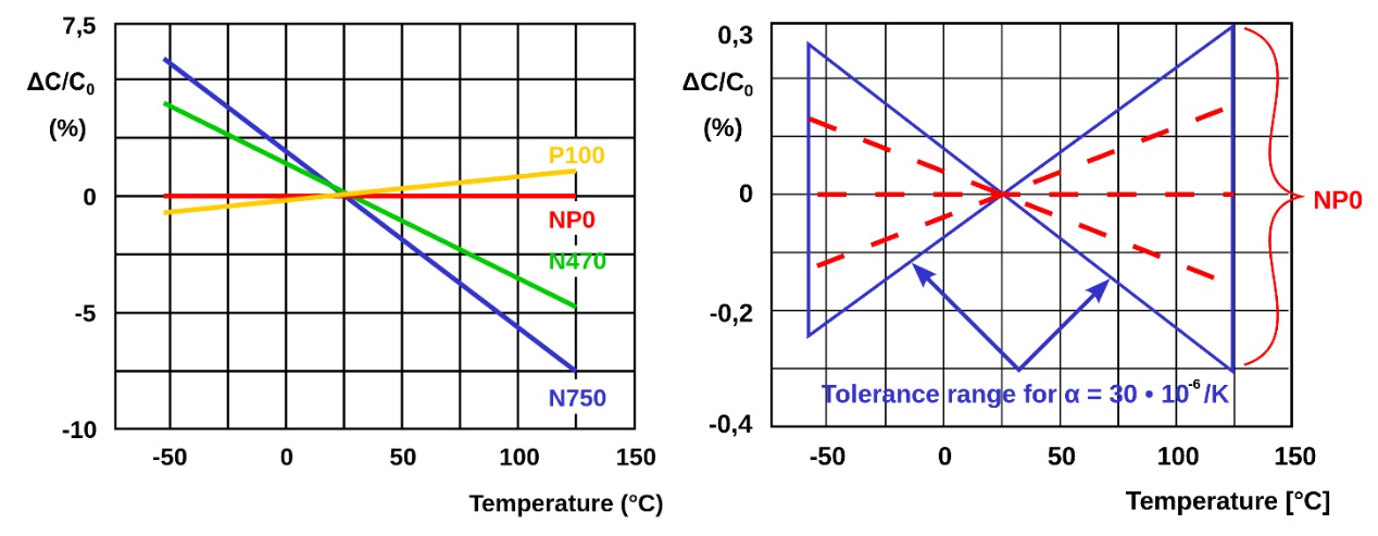
Require NP0 MLCCs for CT and Control Loop circuits:
NP0 refers to a dielectric class with zero temperature coefficient, ensuring stable capacitance across a wide temperature range. Unlike standard MLCCs, NP0 capacitors maintain exceptional temperature stability, with minimal capacitance variation across a broad temperature spectrum. They also show insignificant dielectric losses and almost no voltage coefficient. Naturally, this stability comes at a higher cost.
However, to prevent thermal drift in critical circuits, such as in the use of a CT (timing capacitor for setting converter switching time) and control loops, it's essential to use NP0 MLCCs.
The first diagram below demonstrates how capacitance changes with temperature for Class 1 ceramics. The second diagram shows the temperature dependence of capacitance for an NP0 MLCC, highlighting its tolerance range.
Support both ATX12V and ATX12VO with the same PSU:
I find it ironic that when Intel releases the new ATX12VO PSU and motherboard form factor, which is more efficient and user-friendly, the media criticizes it because adopting a new ATX12VO motherboard means needing a new ATX12VO power supply (which isn’t entirely true as my team and I developed a 24-pin to ATX12VO 10-pin motherboard connector with a built in boost converter for the +12VSB so any ATX PSU could be used: https://www.corsair.com/us/en/p/pc-components-accessories/cp-8920272/), turning customer sentiment against it. In contrast, when Nvidia launches new graphics cards that not only require a new power connector (first the 12-pin micro-fit and then the 12VHPWR which then became the 12V-2x6) but also a new power supply to manage the power excursions of these power-hungry GPUs (ATX 3.x), the media response is silent.
Ideally, it would be good to have both 24-pin and 10-pin connectors on PSU. The PSU’s main PCB standby rail would still be +5VSB, but this can convert to +12V using a small boost converter on the modular PCB for when an ATX12V motherboard is used.
I attempted to patent a circuit that would "sense" which motherboard connector was attached, and if the ATX12VO was connected, the +5VSB would automatically boost to +12V while the DC-to-DC circuit for minor rails would deactivate to enhance efficiency. Unfortunately, I was informed that there was too much prior art to patent this. ¯\_(ツ)_/¯
Enermax claims the title for the first PSU that supports both ATX 3.0 and ATX12VO simultaneously (https://hwbusters.com/psus/enermax-platigemini-1200w-atx-v3-1-atx12vo-psu-review/), but this PSU has two separate standby rectifiers inside that function concurrently, regardless of the motherboard type being used. Not ideal as this requires more components, increased cost, etc.
Keep your quality control engineers happy:
While the contributions of mechanical and electrical engineers during product development are evident and significant, it's essential not to overlook the role of engineers who oversee suppliers. These engineers ensure that components adhere to specifications and that standard operating procedures are followed with precision and diligence.
Without their oversight, even a flawlessly designed product can encounter issues. This is particularly true with the tendency in Chinese culture to opt for "good enough" solutions, which can lead to substituting approved components with cheaper alternatives that may not meet your performance standards, only appearing to save costs for your OEM.
Additionally, once a product is in the market, customers might encounter rare issues not identified during development. It's crucial for a company to have a product engineer who can quickly identify, address, and resolve these problems before they become widespread and damage the product’s reputation.
Use RTV to help silent magnetics:
RTV stands for Room Temperature Vulcanizing and is a type of silicone sealant or adhesive that hardens at room temperature. Magnetic coils can vibrate at high frequencies due to electromagnetic forces, leading to an audible whining sound. Applying RTV silicone to the coil can dampen these vibrations and reduce the noise.
It is crucial to use a neutral cure RTV silicone. Standard RTV silicones, like those used for making gaskets, often emit acetic acid during curing, which can corrode electronic components. You’ll realize you’ve gone wrong if you start to smell a vinegar smell coming from your PSU. Neutral cure RTVs, such as oxime or alcohol cure types, are safe for electronics. Look for RTVs that are labeled as “neutral cure” and “safe for electronics.”
When applying RTV, consider the heat dissipation of nearby components. Regular RTV is not very thermally conductive, and applying it to components like diodes and MOSFETs can trap heat, similar to covering them with a blanket. The person applying RTV needs to be well-trained to apply it only where necessary.
There are materials with excellent thermal conductivity used to encapsulate electronics, known as potting compounds, but they are significantly more expensive. Potting compounds are typically used when components need to be sealed from environmental factors. A process known as “encapsulation”. This process can keep out moisture, reduce vibrations, and even protect against reverse engineering, as removing potting compounds can damage the components on the PCB. I've used potting materials with thermal conductivity as high as 2 or 3W/m-k to create completely passive PSUs by evenly dissipating heat to the PSU housing. However, these compounds are very costly, even in China. So, until they become more affordable, I will continue using typical 1-part neutral cure RTV for my projects.
All hail the modular power supply!:
It’s hard to believe that before 2003, the DIY PC industry had never even seen a modular power supply. A modular power supply is one where the user can choose what cables to attach for use to power their devices inside the PC.
Unused cables can be stored away for future use. This allows for cleaner builds since there are fewer, unterminated cables within the PC. In 2003, Hank Baron of Performance-PCs in Palm Bay, FL, cut the cables short on a power supply and installed connectors on what was left of the cables. He then installed extensions to allow the user to install and route the cables they needed throughout their PC.
In 2004, Ultra Products came out with the “X-Connect” power supply, which took Baron’s idea a step further. Instead of connecting cables to cables, a PCB was mounted inside the PSU’s housing and the connectors were mounted to it. This made installation even cleaner since there were absolutely no unused cables present. Only unused connectors on a PCB.
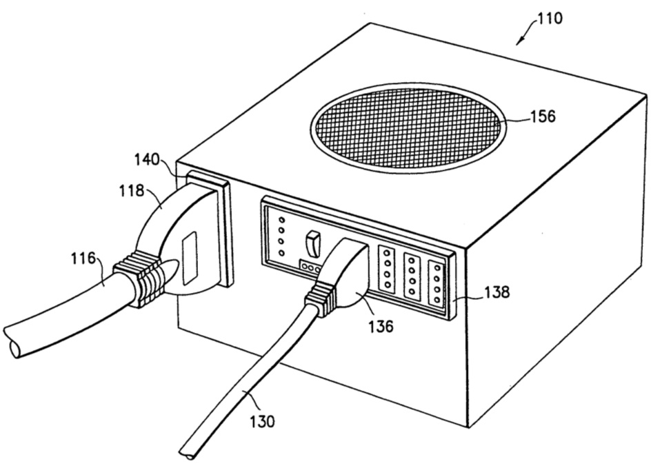
A drawing from the Ultra Products' patent for a modular power supply.
Between 2005 and 2007, nearly every PSU brand in the world had their own version of a modular power supply. But they all executed the design in a similar way. The same wires that would normally be fed outside of a hole in the PSU’s housing were soldered to a secondary PCB where the modular connectors resided.
I believe it was in 2010 that designs changed drastically. To my recollection, Seasonic changed the way modular PSUs were built with their “KM” platform by making the modular PCB an integral part of the PSU’s design. Not only getting rid of the cables that join the main PCB to the modular board, but by putting essential components on the modular PCB essentially utilizing it as part of the overall design, as opposed to a second thought.
At this point, you’re probably wondering why I’ve given you a history lesson in modular power supplies. Well, they say history is good to know if you want to avoid making mistakes in the future.
Sometimes, design decisions are made to cut costs, such as opting for a semi-modular or non-modular PSU. These choices can lead to savings due to a smaller PCB and fewer connectors in a semi-modular PSU or the absence of a modular PCB and connectors in a non-modular unit. However, I've often noticed that output filtering components, typically found on the modular PCB, are missing altogether from the PSU! Complex modular PCB designs generally include DC to DC buck converters for minor rails, and it's common to see output inductors and capacitors mounted on the modular PCB. Therefore, when an ODM chooses to "leverage" an existing platform intended to meet specific criteria as a fully-modular power supply, it's not unusual for the final product to lack components that help reduce ripple and noise. Adding these parts back to the main PCB would require a larger PCB, negating the benefits of using an existing platform's PCB. The takeaway here? If a platform is designed as a modular power supply, don't alter it. While removing modularity might lower costs, the platform should be initially designed as a non-modular power supply.
Customers should be aware of the quality of cables:
Many customers unfortunately don't grasp the difference between a high-quality cable and one that is simply easier to use. Your cable could be crafted from 99.99% pure oxygen-free copper wires with excellent conductivity, but if it lacks flexibility, users often label it as "cheap." This misconception is regrettable because creating a "cheap" flexible wire is simpler than making a premium cable that might be a bit stiff.
Out of morbid curiosity, I once bought a 16 AWG PCIe extension cable from a brand famous for their "super flexible, easy to use cables." The cable I got featured a silicone jacket, which certainly within itself made the cable very pliable. And while silicone is known for its flexibility and is pricier than standard PVC insulation, it is not as costly, ounce for ounce, as copper.
The insulated wire had an overall outer diameter of around 3mm. This would be typical for a 16 AWG wire. However, upon cutting into the wire, I discovered the insulation was quite thick—over 1mm thick. The exposed copper wire was under 2mm in diameter. Without the jacket, a 16 AWG wire should measure over 3mm thick. This resembled more of a thickly jacketed 18 or 20 AWG wire. I counted roughly 100 very fine strands of copper, which explained its flexibility! Although I trust these wires can handle 14A of current, I wouldn't rely on them for long periods. Generally, you want some safety margin, which is why most of us opt for 16 AWG wires for PCIe cables in the first place! It seems to me what they’re trying to do is put a thick jacket on UL1061 wire in hopes that it’s “close enough” to meet UL1015.
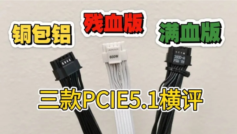
Could be worse. This user found copper clad aluminum wires in his PCIe cables! Higher temperatures and lower voltage! https://www.bilibili.com/video/BV1kWgkzAESU/
Using more copper strands:
It's not unusual for the 16 AWG wires in a PSU's cable to consist of 65 strands, each with a diameter of 0.158mm. The more strands there are with smaller diameters, the more flexible the wires become. For instance, 165 strands of 0.1mm are more flexible than 65 strands of 0.158mm, and 260 strands of 0.08mm are about as flexible as possible. However, using a higher number of finer copper strands comes with its own set of advantages and drawbacks.
Finer copper strands enhance cable flexibility, but they also increase costs due to the manufacturing process. A common discussion point is that finer strands may have higher DC resistance because of the potential for air gaps between them. On the upside, finer copper strands offer better heat dissipation because of the increased surface area provided by the additional strands. Personally, I've used 0.08mm copper strands in my PSU wires without any adverse effects. The main challenge I've encountered is that they're harder to crimp.
Recognizing the hardness of your wire’s jacket:
The insulation on wires is gauged for hardness using the Shore hardness scale, which assesses how well a material resists indentation. Many people recognize the Shore scale from its use with skateboard or in-line skate wheels, where the Type A Shore hardness number is usually marked on the side. A lower number indicates a softer compound.
Hardness is determined with a durometer. For instance, if you measure the very flexible jacket of a silicone-insulated wire, you'll find a Shore A reading of 50. In contrast, a typical PVC jacket will show a Shore A hardness of 90. Insulation that's too soft can get marked up easily, while too-hard insulation makes wires tougher to bend. Additionally, unless you're in direct communication with the wire manufacturer, determining the exact Shore hardness can be tricky. Even if you're informed about the expected insulation hardness, Chinese suppliers may not always provide the accurate figure. I highly suggest having a couple of durometers on hand; they cost only about $30 to $50 each.
The importance of proper crimping:
This section you're about to read isn't a typical "wish list" like the previous ones. It's not about rules like "never use rod inductors" or "always use PWM fans." Instead, it's more of a warning. In today's world of overheating GPU power cables, the quality control of a simple cable can make the difference between a customer using their PC without any issues and your brand becoming a joke on Reddit, leading to costly replacements for their graphics card.
In the typical production process, the finished cables are tested for continuity, but even a milliOhm meter is not necessarily going to capture a poor crimp as a significant load is required to produce enough resistance for a meter to measure. And outside of destructive analysis, one requires an expensive X-ray machine to spot bad crimps within an assembled cable. This is why it is best to catch any bad crimps the moment they are made and before any further assembly is done. At work, we use this document almost religiously, especially lately with he advent of the new 12V-2x6 connector:
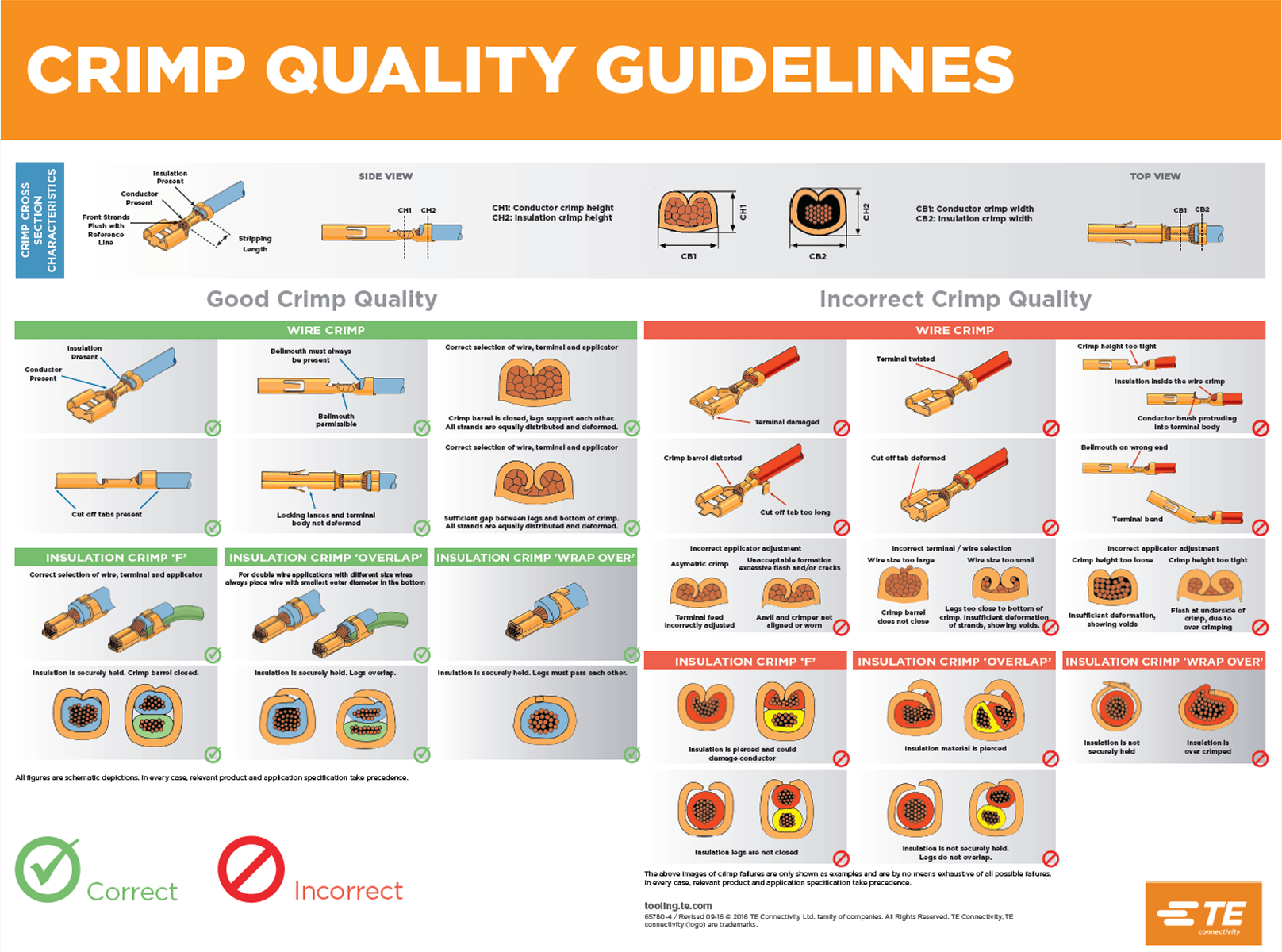
Click for larger image
The entire document that these guidelines come from can be found here: https://www.te.com/content/dam/te-com/documents/application-tooling/global/Where%20Form%20Meets%20FunctionA-1-1773838-7.pdf
In summary:
I hope this article has provided some insight for anyone interested in PC power supplies, whether you're part of the industry, a consumer curious about the workings and construction of power supplies, or a reviewer who doesn't typically delve into details beyond the type and origin of capacitors used.
I've decided to make this a living document. As I come up with new things to add, I will add them. There is always a lot to talk about.