How to Avoid Power Supply Pitfalls
Small details can make the difference between a quality power supply unit and a problematic one
When one looks at purchasing a power supply, it is often done with little research and using only the most basic information available. Consumers may only look for the following features:- The presence of an 80 PLUS badge, which is just one aspect of a power supply and this classification can be faked.
- The total output wattage printed on the box, which may represent the actual output, but could also be a fictitious number.
- Whether the power supply includes cables the customer believes they will need for their build without considering modularity, wire quality, and other aspects of cable quality.
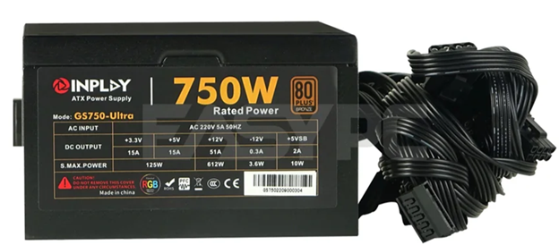
Example of a “fake” 750W. Not there is only 612W on the +12V rail. The only way to get 750W is if every rail was fully loaded, which is a very unrealistic scenario. The 80 PLUS on this unit is also fake. The unit tested by 80 PLUS is different than what is being sold.
To make an informed decision, it helps to understand a bit more about how a power supply is built. This document outlines some of the parameters that can drive quality and cost of a power supply. Rather than delving into complex design architectures and their pros and cons, this guide offers a straightforward explanation of common terms you'll encounter in reviews and testing, clarifying how these elements influence a power supply's real-world performance, overall level of quality, and reliability.
Common Issues and Their Causes
What is Ripple and Why High Ripple is Bad: Your home supplies alternating current (AC) power from the wall, but your computer components require directional current (DC). This is the purpose of your computer’s power supply; to convert AC to DC. When converting AC to DC, AC becomes a part of the DC output. In a switch mode supply the process of converting AC to DC, back to AC, and then finally back to DC again, can generate high-frequency noise and harmonics known as ripple.
High ripple can cause the capacitors in your devices (motherboard, GPU, etc.) to overheat, leading to the evaporation of the electrolyte inside the capacitors used on these devices, which has the potential to cause catastrophic failure.
The smaller capacitors on the output side of a power supply help filter out as much ripple as possible. However, increasing their capacitance to filter out more ripple also raises the in-rush current because all these capacitors need to be fully charged to reach the desired output voltage. Output voltage regulation can be affected when power excursions, also known as transients, partially drain the capacitors, requiring them to recharge to maintain proper output voltage. This also stresses the switching components. So, it’s best to have the right balance of capacitance and an acceptable amount of filtering for ripple.
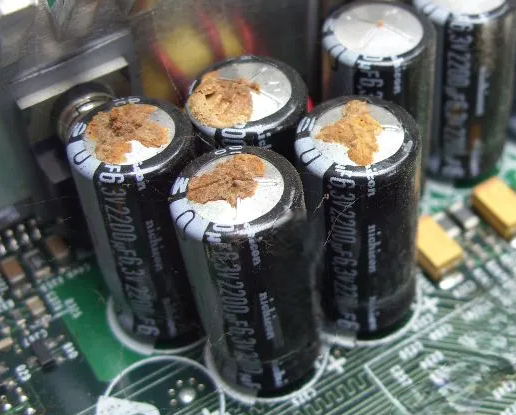
Even Japanese caps can suffer the consequences of too much ripple.
Poor Transient Response: Transient response refers to the behavior of output voltage as the PSU transitions from one load to another. It’s how we describe how a PSU responds to sudden load changes before settling into a steady state. For example, a sudden change in load from low to high may cause output voltage to drop. This can be normal behavior, but the question we ask is how long does the PSU stay in this state before the output voltage recovers to a nominal voltage?
Poor transient response in a power supply can cause a variety of problems, including voltage fluctuations, system instability, and potential damage to sensitive components. Specifically, a slow or poorly regulated transient response can lead to voltage drops (undershoots) or spikes (overshoots) that exceed a device's operating limits, causing it to malfunction, reset, or fail.
Quality Control Issues: Poor assembly practices and lack of quality control can result in premature failures. The manufacturing of power supplies remains largely manual, with automation reserved for premium manufacturers. Before reaching the bulk solder machine, components must be manually placed into the PCB. While these machines excel at consistent high-volume soldering, their output quality hinges entirely on proper input preparation.
When misalignments or insertion errors emerge post-soldering, technicians must perform "touch-ups," a process where operators visually inspect each board and manually correct defects using handheld soldering irons. This delicate work invites numerous potential issues: improper heating creates fragile connections or damages components, while human error leads to either excessive soldering creating shorts or insufficient soldering causing weak links. Particularly insidious are poorly made solder joints that initially pass burn-in testing only to fail days later during shipping, when components work loose from their moorings due to poor soldering.
Low or No Power Factor Correction: Most PSUs in the EU and North America have power factor correction, and a high-power factor correction is required in order to achieve either an 80 PLUS or Cybenetics certification level of efficiency. However, some parts of the world do not require power factor correction. Additionally, some brands often “fake” their efficiency badges (this is when you see badge that look like 80 PLUS but say “85 PLUS” or “90 PLUS”, or the badge will look like an 80 PLUS badge, but there is no corresponding 80 PLUS report.
Power factor is a crucial metric in electrical systems, serving as an indicator of how proficiently electrical power is being transformed into productive work output. Unlike the straightforward efficiency percentage calculation of output divided by input, power factor specifically reveals how effectively the current drawn from the source is being utilized to accomplish genuine work.
For us to calculate power factor, we need to understand three terms used in the calculation: apparent power, real power, and reactive power.
Apparent power represents the total power supplied to the circuit and is measured in Volt Amps (VA).
Real Power is measured in Watts (W) and represents the actual AC power that performs tangible work—such as powering a motor or illuminating a bulb. In the context of this article, it refers to the power that is ultimately converted into DC.
Reactive power is the elusive energy that fluctuates back and forth between the source and reactive components, such as the inductors and capacitors in the power supply, without performing any useful work. Reactive power is measured in Volt Amps Reactive (VAR).
By taking the real power and dividing it by the apparent power, one obtains the power factor.

Reactive power is considered problematic because it increases the overall current flowing through the power supply. Although it doesn't supply useful energy to the computer that the PSU is powering, it still adds to the current that power lines, transformers, and generators need to manage. This additional current results in more resistive losses on the power grid, generating heat and wasting energy.
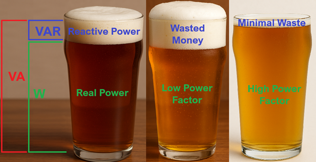
The "beer analogy" illustrating reactive power vs. real power.
Hold-Up Time Issues: Hold up time is a specification for how long the PSU can continue to deliver stable, regulated DC output power after there is an interruption of AC input power, which can happen when a brown out occurs.
Hold-up time specifications vary between power supply units. Under the original ATX12V standard, PSUs needed to maintain power for 17ms at 100% load, with longer durations possible at lower loads. The newer ATX 3.1 standard has shortened this requirement to 12ms at full load.
Regardless of which specification a PSU follows, it must maintain proper voltage levels during this hold up period (keeping +12V outputs above +11.4V, for instance) to safeguard the connected components from potential damage.
Proper Fan Design and Fan Control: Fans used in power supplies need to have a higher static pressure specification (measured in mmH2O, or "millimeters of water column"), much like a radiator fan with dense, tightly packed blades, versus your typical case fan with its wider, more sweeping design which would focus on CFM (air measured in cubic feet per minute).
The layout of the PSU's printed circuit board is engineered to take advantage of the swirling, turbulent airflow patterns inside the cramped PSU housing. A fan with high-static pressure, typically outfitted with a plastic baffle to direct some of the rushing air where it needs to go, will force cooling currents to specific heat-generating components that tend to run dangerously hotter than their neighboring parts.
Chinese Brand Components and Questionable Specifications: It’s no secret that, due to supply chain convenience, most power supply components are made in China. Not just finished goods, but the actual components used to manufacture these goods. Japanese capacitors? Made in China. German MOSFETs? Made in China. Korean ICs? Made in China. And this is all good as these parts follow strict quality control measures. But lately, we’ve seen a number of China-based brands producing products with datasheets that match their international brand counterparts, but in our testing we’ve often found that the specs of these Chinese brands do not align with their spec sheets.
This is particularly problematic with Metal Oxide Semiconductor Field-Effect Transistors (MOSFETs). We’ve found that sometimes they run hotter, despite having the same RDS (on) (more on that below) as their more expensive counterpart. This challenges our ability to properly cool the device, while still maintaining a low-noise product. A higher operating temperature also increases the risk of thermal runaway. Thermal runaway is a self-reinforcing heating cycle. As a MOSFET conducts current, it dissipates heat from conduction and switching losses. As the junction temperature rises, key parameters (like RDS (on), threshold voltage, leakage current) change. These changes increase power loss even further, causing more heating. Inevitably, the MOSFET may exceed its Safe Operating Area (SOA), leading to destruction.
RDS (on) is the drain-to-source resistance of a MOSFET when it is fully turned on (saturated). It determines how much the MOSFET resists current flow during conduction. The higher the ACTUAL RDS (on), the hotter the transistor.
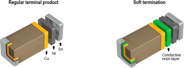
Not Using Soft Termination MLCCs in “High Risk” Locations Can Cause Premature Failures: Multilayer Ceramic Capacitor (MLCC) is a widely used surface mount technology (SMT) capacitor found in electronic devices. These passive components store electrical energy and are mainly utilized for decoupling, filtering, bypassing, and timing tasks within circuits.
When an MLCC is positioned less than 2mm from the edge of a Printed Circuit Board (PCB) or less than 3mm from a PCB screw hole, a soft termination MLCC must be employed. Failing to do so can result in these small components either breaking or detaching from the PCB, leading to intermittent connections.
For power supply units with modular PCBs that use MLCCs, it is recommended to exclusively use soft termination MLCCs. This precaution is necessary because the insertion and removal of modular cables can cause the PCB to flex, potentially damaging the MLCC or its connection to the board.
Why Are Some Power Supplies “230V Only": By Watt’s law, lower voltage requires higher current for the same power, so 100–127V regions such as North America, Japan, Taiwan, and other areas need bulkier, more heat-resistant rectifiers, which raises costs. If you're designing for countries where residential voltages are 220V or higher, there's no need for a rectifier that can handle as much current. Nevertheless, brownouts can reduce voltage significantly below what is considered normal. Hence, it's crucial to have proper protections in place to prevent the power supply from failing catastrophically if the input current surpasses the bridge rectifier's capacity.
Why You Can’t Find a 2000W+ PSU That Works in Your American Home: Residential voltages vary widely: Japan uses 100V; Taiwan, Cuba and many U.S. outlets measure about 115V (nominally 120V); parts of South America and the Caribbean use 127V.
For example: In the U.S., NEMA 5-15 outlets are limited to 15A continuous (120V × 15A = 1800W AC, or ~1620W DC at 90% efficiency). Real-world loads and the 80% rule on 20A breakers typically cap usable PSU power around 1.6 kW. While 20A NEMA 5-20 circuits exist, they’re uncommon in homes.
On 220–240V mains, a 10A circuit delivers 2200W AC (nearly 2,000W DC at 90% efficiency). U.K. plugs handle up to 13A and Schuko outlets up to 16A, so higher-power PSUs are more practical there.
Poor Cable Quality
An often-overlooked aspect of power supplies are the cables that are included, the materials used to construct them, and how well they are constructed. The following three points are the biggest pitfalls we’ve seen when “cheaper cables” are provided.
Aluminum Wires: Copper-Clad Aluminum (CCA) wire is an aluminum wire with a copper coating, while pure copper wire is made entirely of copper. Pure copper is superior in terms of electrical conductivity, flexibility, and resistance to heat and corrosion. CCA is cheaper, but it is not recommended for many applications, especially where electrical safety and performance are critical, due to its higher resistance (55 to 60% higher for aluminum versus copper wire of the same gauge) and lower melting point. Copper is also more flexible and less prone to breaking after repeated bending.
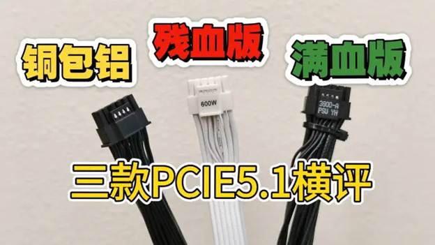
This user found copper clad aluminum wires in his PCIe cables! Higher temperatures and lower voltage! https://www.bilibili.com/video/BV1kWgkzAESU/
Incorrect Wire Gauge for Intended Application: Copper isn’t cheap. The thicker the copper, the more expensive the wire. The problem is that thinner copper has more resistance than thicker copper. Unfortunately, wire gauge is not often marked on cables, and a customer may perceive a smaller gauge wire used in a cable as a better-quality cable because they have better flexibility.
Lower Rated Temperature Rating for a PVC Jacket: Polyvinyl Chloride (PVC), also known as a plastic polymer, insulation softens and can deteriorate over time when exposed to temperatures exceeding its rated limit. The breakdown of the PVC insulation can compromise the wire's ability to safely carry electrical current. Over time, this can lead to cracks, shorts, and potentially even electrical fires.
One example is the 12V-2x6 cable. The connectors are generally rated at 105°C, and yet we occasionally see some melting. We have seen some wire insulation used in a few 12V-2x6 cables rated at only 80°C to 85°C. PVC, being a thermoplastic material, softens at elevated temperatures, which can increase its susceptibility to deformation and mechanical damage. This softening can lead to the wire jacket separating from the connector or becoming damaged, exposing the conductors to potential hazards.
Better Parts Do Mean Lower Noise
Toroid Coils Inductors vs. Rod Coils: A toroid coil inductor consists of a ferromagnetic ring wound with copper wire. A rod coil inductor uses a cylindrical core wrapped along its length. The only real benefit of a rod core is lower material and labor cost.
Toroid cores, by contrast, generate less audible noise. The magnetic forces within do not cause bending in the core—only compression or tension—and their circular design offers better mechanical stability.
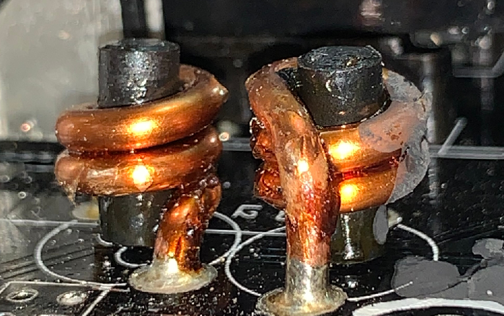
Example of rod coils used on the secondary side of a lower end PSU.
The impacts of rod coils tend not to be evident in the lab. I once worked on a project that used rod coils on the output stage. Lab testing on our Chroma didn’t detect audible noise. But real-world usage told a different story: complaints came pouring in, and we quickly switched to toroids.
Using Sendust as a Ferromagnetic Material for Inductors: Sendust is a magnetic alloy that was created as an alternative to iron powder and other magnetic core materials used in inductors and transformers. It is made up of 85% iron, 9% silicon, and 6% aluminum.
Sendust is highly regarded because it has lower eddy current losses and does not produce mechanical vibrations when exposed to magnetic fields. In our industry, the primary drawback is its cost. Additionally, since Sendust is a sintered compound, it tends to be more brittle than other materials. Consequently, Sendust inductors might need to be slightly larger to match the energy storage capacity of an iron core, so space limitations in smaller designs should be considered.
I have been using Sendust almost exclusively for about 10 years. We’ve found that the small investment made to improve audible noise is well worth it as customer complaints have been reduced significantly.
Using Split-Windings as Opposed to Single-Windings for the Power Factor Correction Inductor: Once again, we have an optimal solution that requires additional space. However, if space permits, we highly recommend using split-windings.
As the term suggests, a single-wound inductor consists of a single continuous copper wire coil wrapped around the core. A split-wound inductor, also called a bifilar-wound or common-mode choke, divides the copper wire into two separate windings around the core. This configuration effectively blocks common-mode noise, making it perfect for use as a PFC choke since it helps reduce electromagnetic interference (EMI) and radio frequency interference (RFI). Common-mode noise often arises from parasitic capacitances between the MOSFETs and ground.
Even though the split-wound inductor is larger, its cost should not significantly exceed that of a single-wound inductor, provided the manufacturing plant uses an automated process to produce them.
Automated machine manufacturing a split-wound inductor.
We started using the split-wound inductor for our PFC chokes when we started to see some high-frequency RFI results in some of our designs. Unfortunately, due to the slightly larger size, we can’t use them in smaller form factors like SFX.
Using RTV to help silence magnetics: Room Temperature Vulcanizing (RTV) is a type of silicone sealant or adhesive that hardens at room temperature. Magnetic coils can vibrate at high frequencies due to electromagnetic forces, leading to an audible whining sound. Applying RTV silicone to the coil can dampen these vibrations and reduce the noise.
It is crucial to use a neutral cure RTV silicone. Standard RTV silicones, like those used for making gaskets, often emit acetic acid during curing and can corrode electronic components, which will make your PSU smell like vinegar. Neutral cure RTVs, such as oxime or alcohol cure types, are safe for electronics. Look for RTVs that are labeled as “neutral cure” and “safe for electronics.”
When applying RTV, consider the heat dissipation of nearby components. Regular RTV is not very thermally conductive and applying it to components like diodes and MOSFETs can trap heat, similar to covering them with a blanket. The person applying RTV needs to be well-trained to apply it only where necessary.
There are materials with excellent thermal conductivity used to encapsulate electronics, known as potting compounds, but they are significantly more expensive. Potting compounds are typically used when components need to be sealed from environmental factors. A process known as “encapsulation”. This process can keep out moisture, reduce vibrations, and protect against reverse engineering as removing potting compounds can damage the components on the PCB. We’ve used potting materials with thermal conductivity as high as 2W/m-k or 3W/m-k to create completely passive PSUs by evenly dissipating heat to the PSU housing. However, these compounds are very costly, even in China. So, until they become more affordable, I will continue using typical 1-part neutral cure RTV for its power supplies.PSU Protections
Power supplies should have what are referred to as “protections.” These protections are monitored by integrated circuits within the PSU. Whether the ICs are analog or digital, what protections they provide can vary from PSU to PSU. Ultimately, one would want a power supply that offered every possible protection available. The following are a list of protections one should find in their power supply unit.
Over Current Protection (OCP): This protection activates when rail current exceeds predetermined thresholds. Many power supply manufacturers set higher OCP trigger points to accommodate power spikes from components like graphics cards. Implementing OCP requires two key elements: high-precision, low-resistance shunt resistors and a compatible supervisor IC. These shunt resistors measure PSU output current by detecting voltage drops across themselves.
Over Power Protection (OPP): When a power supply unit is pushed beyond its rated capacity, this protection activates as a safeguard. Most manufacturers build in a buffer zone, setting the OPP threshold approximately 50W-100W (sometimes more) above the PSU's stated maximum wattage. For PSUs with a single +12V rail, where over-current protection rarely comes into play, the OPP mechanism serves as the primary defense, automatically shutting down the unit if the +12V rail draws excessive power.
Short Circuit Protection (SCP): This protection functions as a vigilant guardian of your power supply unit, continuously checking the output rails for dangerously low impedance levels (below 0.1Ω). When this condition is detected, the SCP immediately triggers an emergency shutdown to prevent potential damage or fire hazards.
An interesting thing about SCP in most power supplies is that it typically only functions if there is a short to ground. In many PSUs, if two live wires carrying different voltages touch, the SCP won't engage at all. Computer enthusiasts once exploited this limitation to create makeshift voltage reducers for cooling fans by connecting +12V and +5V lines to produce +7V. Though one could modify a PSU to safely accommodate such tricks, it remains a risky practice best avoided. Modern, higher-quality power supplies have addressed this vulnerability; their SCP systems now activate whenever any two voltage lines touch each other or ground.
Over Voltage Protection (OVP): If an output drops below a voltage that is considered safe for the components they are providing power to, OVP should shut down the PC to prevent potential damage to the components.Under Voltage Protection (UVP): If an output increases in voltage to a value that is considered unsafe to the components they are providing power to, UVP should shut down the PSU to protect potential damage to the components.
Over Temperature Protection (OTP): Power supplies with this protection typically feature a thermistor, which is a thermally sensitive resistor, mounted on the +12V rectification, often the same location where the fan control unit's thermistor resides. This component monitors the temperature of the +12V MOSFET, diode or secondary heatsink (depending on design) and triggers shutdown when readings exceed safe thresholds. This safeguard is essential, as excessive temperatures, whether from component overload or fan failure, can cause permanent damage.
In conclusion…
A PSU’s overall level of quality and reliability cannot be reduced to efficiency badges, output claims, or cable counts. Reliability comes from design discipline, component selection, manufacturing practices, and adherence to rigorous electrical performance standards.
Ultimately, your power supply is the foundation of your entire system. Saving a few dollars up front on a bargain unit may look tempting, but the hidden risks, like unstable power, component failures, or total system loss can cost far more in the long run. A quality PSU is not just about wattage on the box. It’s about safety, stability, and peace of mind. Think of it as an investment in the health and reliability of your entire PC build.